Why Oil Isostatic Presses Are Important in Composite Materials Manufacturing
Uniform Pressure, Precise Temperature Control and Continuous Processing for FCCL, Advanced Composites, New Energy Materials and Laminated Panels
As advanced composite materials continue to develop across the electronics, aerospace, automotive, hydrogen energy, solid-state battery, and construction industries, manufacturers are facing increasingly demanding requirements for pressure uniformity, temperature stability, material consolidation, thickness accuracy, and production efficiency.
In modern composite materials manufacturing, the performance of the finished product is closely related to the stability of the production process. Uneven pressure, inconsistent temperature, insufficient consolidation, and thickness variation can affect bonding quality, material density, dimensional stability, and downstream processing performance.
For these reasons, oil isostatic presses and continuous oil-pressure pressing systems are becoming increasingly important for composite lamination and multilayer material processing applications.
An appropriately designed oil-pressure pressing system can provide controlled pressure transmission across the effective pressing area while maintaining stable processing temperatures. When integrated into a continuous production line, this technology can support consistent processing of multilayer composites, functional films, electronic laminates, new energy materials, and composite panels.
What Is an Oil Isostatic Pressing System?
An oil isostatic pressing system is designed to transfer controlled hydraulic or oil pressure through a pressure chamber to generate a relatively uniform pressing force over the effective working area.
In a continuous pressing configuration, the oil-pressure chamber is incorporated into the pressing structure. Pressure is transferred through the pressing system between the grooved pressing plate and the steel belt, creating controlled contact pressure across the material being processed.
This configuration is particularly suitable for multilayer materials in which different components may have different thermal expansion characteristics, viscosity, compressibility, and deformation behavior.
During composite lamination, insufficient or uneven pressure may result in incomplete bonding, non-uniform resin distribution, voids, thickness variation, or inconsistent density. Uniform pressure distribution therefore plays an important role in achieving stable product quality.
Continuous Composite Material Processing from Unwinding to Finished Product
The pressing process is only one part of a modern automated composite manufacturing line.
A complete continuous production system may integrate multiple stages, including:
This continuous production configuration allows materials to move through the processing line without repeated loading and unloading.
The pressing section consequently becomes a critical process stage connecting material preparation with final product formation.
By integrating material handling, heating, pressing, cooling, inspection, thickness measurement, and downstream cutting or winding, manufacturers can establish a more consistent and efficient production workflow.
Continuous Composite Lamination and Pressing Process
The process begins with multiple roll unwinding stations, where different material layers are introduced into the production line. The layers are then laminated and inspected before entering the preheating section.
During the hot pressing stage, controlled pressure and temperature are applied to promote material consolidation and bonding. The material subsequently passes through cooling or cold plasticization processes before entering online thickness measurement and downstream slitting and winding systems.
This continuous configuration is particularly beneficial for large-volume manufacturing of standardized composite materials and multilayer functional products.
How Oil Isostatic Pressure Supports Composite Lamination
Composite materials frequently consist of multiple layers, including resin systems, reinforcement fibers, metal foils, polymer films, and functional layers.
Each material can exhibit different thermal, mechanical, and rheological characteristics. During heating and pressing, these differences can influence material flow, consolidation, and dimensional stability.
A uniform pressing force helps maintain consistent contact between the different material layers.
The main process benefits can include:
Improved layer-to-layer bonding
More uniform resin distribution
Better material consolidation
Reduced thickness variation
More consistent material density
Improved surface flatness
Greater production repeatability
For multilayer composite structures, controlling the pressure distribution over the effective working width is therefore an important consideration when designing a continuous pressing system.
The Importance of Pressure and Temperature Control
Pressure and temperature are two fundamental process parameters in composite lamination.
During hot pressing, the resin system may need to reach a specific temperature range to soften, flow, impregnate reinforcement materials, or bond adjacent layers. At the same time, the applied pressure must be sufficient to consolidate the material structure.
If temperature is too low, resin flow and bonding may be insufficient. If temperature is too high, excessive resin flow, material degradation, or dimensional instability may occur.
Similarly, insufficient pressure may lead to poor consolidation, while excessive or uneven pressure can affect thickness and material structure.
A stable pressing environment helps manufacturers control:
Lamination quality
Resin flow and distribution
Material consolidation
Finished-product thickness
Material density
Surface quality
Dimensional stability
Product consistency
For high-performance composite materials, maintaining stable pressure and temperature throughout continuous production is particularly important.
Density and Thickness Control in Composite Manufacturing
Density and thickness are important quality parameters for composite boards, electronic laminates, functional films, and advanced material structures.
During continuous pressing, the pressing gap and associated process parameters can be adjusted according to the required product specifications.
Controlled consolidation allows manufacturers to produce materials with different thickness and density requirements while maintaining a stable production process.
Thickness accuracy is particularly important for thin-sheet products. Even relatively small variations can influence material consumption, dimensional stability, electrical properties, mechanical performance, and downstream processing.
Accurate thickness management can therefore contribute not only to product quality but also to improved material utilization and manufacturing efficiency.
Advantages of Continuous Oil-Pressure Pressing
One of the major advantages of a continuous oil-pressure pressing system is its ability to process material continuously.
Traditional batch pressing generally requires materials to be loaded, pressed, held under pressure, and unloaded as separate production cycles. Continuous pressing eliminates much of this repeated handling by allowing material to enter and leave the pressing system continuously.
The potential advantages include:
Higher production throughput
Reduced manual handling
Improved equipment utilization
More stable processing conditions
Consistent pressure and temperature control
Easier integration with online inspection
Easier integration with thickness measurement
Simplified downstream slitting and winding
For high-volume composite materials manufacturing, continuous processing can provide significant advantages in productivity and process consistency.
Energy Efficiency and Thermal Stability
Energy consumption is an important consideration in modern industrial production.
Because a continuous pressing system operates under relatively stable thermal conditions, the equipment does not need to repeatedly undergo complete heating and cooling cycles associated with intermittent batch production.
Maintaining stable operating temperatures can help reduce unnecessary thermal losses and improve overall energy utilization, depending on the equipment design, insulation system, production speed, and process requirements.
The combination of continuous material transport, controlled heating, and stable pressure makes continuous oil-pressure pressing technology suitable for high-volume material processing.
Applications of Oil Isostatic Pressing in Advanced Materials
Oil-pressure continuous pressing systems can be configured for a wide range of multilayer materials and composite products.
Copper Clad Laminates and Electronic Materials
Copper clad laminate (CCL) manufacturing requires controlled temperature, pressure, lamination quality, and thickness consistency.
Continuous pressing technology can be considered for multilayer structures involving copper foil and high-performance functional films.
Potential materials include:
TPI films
MPI films
LCP films
PTFE films
PPS films
Copper foil
Functional polymer films
Precise process control can help manufacturers improve lamination consistency and thickness uniformity for advanced electronic materials.
Advanced Composite Materials
Oil-pressure pressing systems can also be applied to multilayer structures combining resin, fiber, polymer, and metal materials.
Potential applications include:
Fiber-reinforced composites
Resin-fiber composites
Metal-fiber composites
Metal laminates
Thermoplastic composites
Thermoset composites
Polymer composite materials
Rubber-based composite structures
These materials are used in aerospace, automotive, transportation, industrial equipment, and other high-performance manufacturing applications.
Hydrogen Fuel Cell and GDL Materials
The development of hydrogen fuel cell technology is increasing demand for precise processing of functional multilayer materials.
Potential applications include:
Fuel cell materials
Carbon paper
Gas Diffusion Layer (GDL)
Diffusion-layer materials
Functional membrane structures
These materials may require controlled pressure and temperature during lamination, consolidation, and thickness management.
Solid-State Battery Materials
Solid-state battery manufacturing introduces additional requirements for multilayer material processing and thickness control.
Potential applications include:
Solid-state battery materials
Cathode materials
Anode materials
Solid-state electrolytes
Multilayer battery structures
Functional separator and interface materials
Stable pressure and temperature conditions can be important for maintaining consistent material structure during continuous processing.
Construction and Decorative Composite Panels
Continuous pressing technology can also be used in the production of composite construction and decorative panels.
Potential applications include:
Wood-based panels
Particleboard
MDF
PVC-faced panels
Melamine-faced panels
Artificial marble
Artificial crystal stone
Honeycomb panels
Multilayer decorative panels
Uniform pressure distribution can help improve bonding between surface layers and substrates while supporting consistent thickness and surface quality.
Automation and Process Control
A continuous oil-pressure pressing system requires coordinated control of multiple production parameters.
Depending on the production configuration, the system may continuously monitor and regulate:
Pressing pressure
Processing temperature
Line speed
Pressing gap
Material thickness
Cooling conditions
Production parameters
Advanced automation reduces dependence on manual intervention and helps maintain stable operating conditions during extended production runs.
For manufacturers operating high-volume production lines, automated process control can improve repeatability, equipment utilization, production efficiency, and quality management.
Oil Isostatic Pressing as Part of an Integrated Manufacturing System
The importance of an oil isostatic pressing system extends beyond the pressing section itself.
As advanced composite materials become thinner, lighter, stronger, and more multifunctional, manufacturers require production systems capable of combining multiple process-control functions.
An effective continuous composite manufacturing system integrates:
Uniform Pressure Distribution + Precise Temperature Control + Thickness Management + Continuous Processing + Automated Monitoring
From roll unwinding and lamination to preheating, hot pressing, cold plasticization, thickness measurement, slitting, and winding, each stage contributes to the final quality of the composite material.
The pressing section therefore serves as an important connection between material preparation and finished-product performance.
Supporting the Future of Composite Materials Manufacturing
The demand for advanced composite materials continues to grow in electronics, aerospace, automotive, hydrogen energy, fuel cells, solid-state batteries, and advanced construction.
These applications require increasingly precise control of material thickness, density, bonding, pressure, and temperature.
Oil isostatic pressing and continuous oil-pressure pressing technology provide an approach for manufacturers seeking stable pressure distribution, controlled thermal processing, continuous production, and consistent material consolidation.
For large-format and multilayer composite materials, selecting the appropriate pressing technology can contribute to improved product consistency, reduced process variation, better material utilization, and higher production efficiency.
As composite material technologies continue to evolve, continuous pressing systems with advanced pressure and temperature control will remain an important part of modern composite manufacturing.
Contact Us
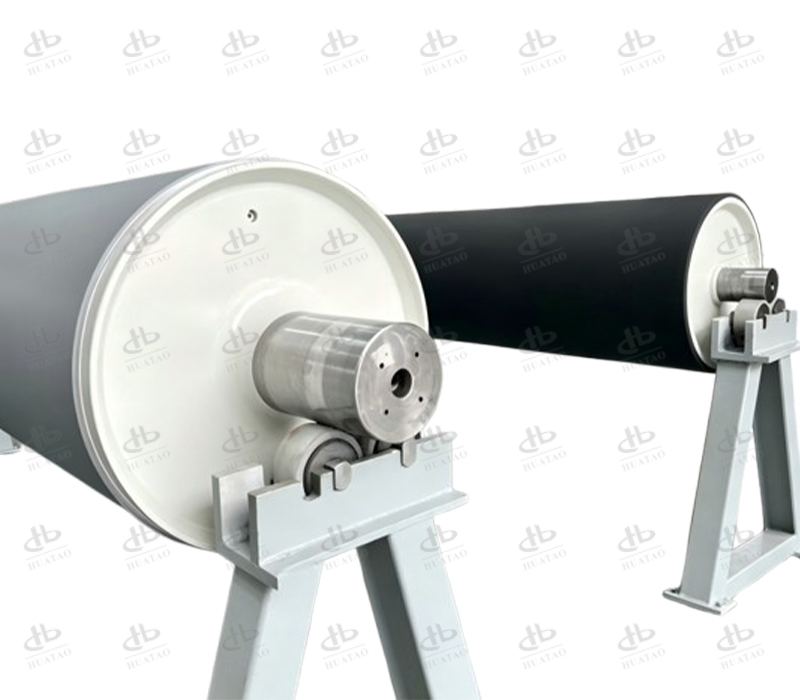
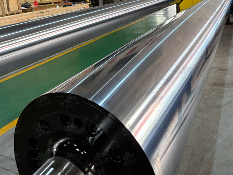
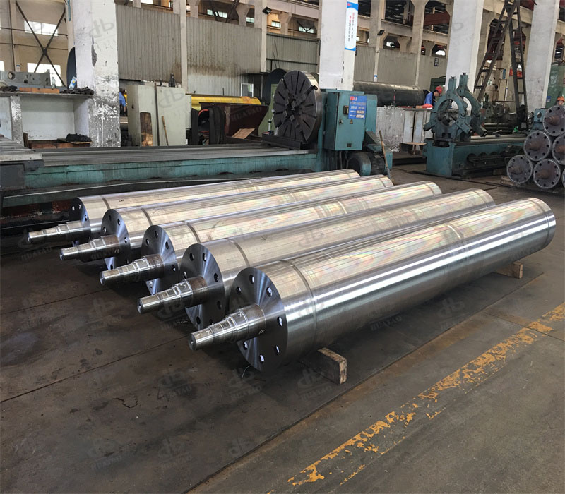
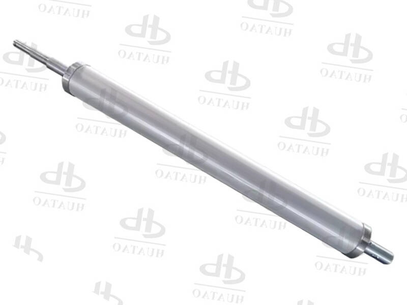
For more information about Heating roll and heating nip roll for oil isostatic presses, continuous oil-pressure pressing systems, composite lamination equipment, or customized pressing solutions for advanced materials, please contact us.
WhatsApp: +86 17743789775
Email: sale05@huataogroup.com
Website: https://www.huataomulti-indusrolls.com/composite-material-industry/
Tags
#OilIsostaticPress
#OilIsostaticPressing
#OilPressurePress
#IsostaticPress
#CompositeMaterials
#CompositeManufacturing
#CompositePress
#ContinuousPress
#ContinuousLaminationPress
#CompositeLamination
#HotPressingEquipment
#PressureControl
#TemperatureControl
#CopperCladLaminate
#FCCLManufacturing
#AdvancedComposites
#ThermoplasticComposites
#ThermosetComposites
#SolidStateBattery
#FuelCellMaterials
#GDL
#NewEnergyMaterials
#LaminatedPanels
Read More

 Related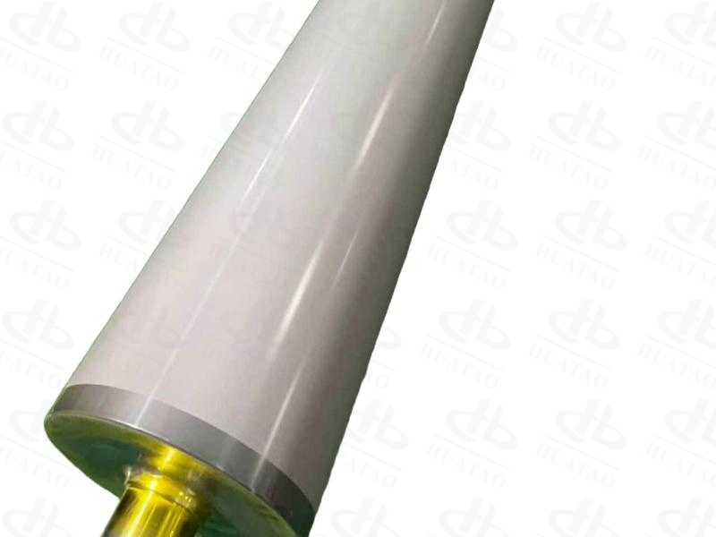
.jpg)